
About this series
Ever since I first saw VPP - the Vector Packet Processor - I have been deeply impressed with its performance and versatility. For those of us who have used Cisco IOS/XR devices, like the classic ASR (aggregation service router), VPP will look and feel quite familiar as many of the approaches are shared between the two.
Segment Routing is a lesser known technique that allows network operators to determine a path through their network by encoding the path inside headers in the packet itself, rather than relying on the IGP to determine the path. Originally created to help traffic engineering of MPLS packets, the concepts were carried forward for IPv6 as well.
In this article I take SRv6 out for a spin, implement some missing features in VPP, and stumble across, and manage to fix a nasty bug in its implementation.
Introduction
SRv6 - Segment Routing for IPv6 - is defined in a number of RFCs.
- [RFC 8402]: Segment Routing Architecture. This document describes the fundamentals. It defines the general concepts of Segment Routing (nodes, segments, and steering) for both MPLS and IPv6.
- [RFC 8754]: IPv6 Segment Routing Header (SRH). This RFC defines the specific IPv6 Extension Header used for SRv6. It explains how segments are listed and how the Segments Left field works.
- [RFC 8986]: SRv6 Network Programming. This one describes the so-called “behaviors” associated with a Segment ID (SID). It defines functions like End (Endpoint), End.X (Layer-3 cross-connect), and End.DT4/6 (VRF decapsulation).
While reading these RFCs, I learn that I can configure an SRv6 path through the network that picks up an ethernet packet on the ingress, and decapsulates and cross connects that ethernet packet to an interface on the egress: an L2VPN using Ethernet-over-IPv6. That sounds dope to me!
SRv6 in VPP - Segment Routing Header
For the dataplane, there are two parts of note. Firstly, when an IPv6 packet arrives with an IPv6 extension header, the so-called Segment Routing Header or SRH, any router supporting SRv6 needs to inspect it. The presence of an SRH changes the forwarding logic from a simple “look at the destination, do a FIB lookup for next hop, and send the packet on its merry way” to a more customized “process the instruction and update the IPv6 headers” kind of thing.
In IPv6, an (almost) arbitrary amount of headers can be chained from the base IPv6 packet header, to the ultimate layer4 protocol header like ICMP, TCP or UDP. In IPv4, this is not the case, there is only the L3 header (IPv4) and the L4 header (TCP/UDP/ICMP etc). These intermediate headers are called Routing Extension headers, and the SRH is the one with type 4.
The fields in this header are:
- Next Header: Identifies the type of header following the SRH. It can be another routing extension header or it might be the Layer4 protocol header like TCP, UDP or ICMP.
- Flags: IANA loves reserving optionality for the future. The authors of SRv6 added an 8-bit flags field, but none of them have been assigned yet.
- Tag: Moar optionality! This 16-bit tag is not defined in the RFC, simply stating that The allocation and use of tag is outside the scope of this document. OK then!
- Segments Left (SL): A counter indicating how many intermediate nodes still need to be visited.
- Last Entry: The index (starting from 0) of the last element in the Segment List.
- Segment List: This is an array of 128-bit IPv6 addresses, listed in reverse order of the path. The first segment to be visited is at the highest index.
- (optional) TLVs: These Type-Length-Value objects can encode other information, like HMAC signatures, operational and performance monitoring data, and so on.
SRv6: Anatomy

Much like magnets, you might be wondering SRv6 Routers: How do they work?. There are really only three relevant things: SR Policy (they determine how packets are steered into the SRv6 routing domain), SRv6 Source nodes (they handle the ingress part), and SRv6 Segment Endpoint Nodes (they handle both the intermediate routers that participate in SRv6, and also the egress part where the packet leaves the SRv6 routing domain).
SRv6: Policies
A Segment Routing Policy is the same for MPLS and SRv6. They are represented by either a stack of MPLS labels, or by a stack of IPv6 addresses, and they are uniquely identified by either an MPLS label or an IPv6 address as well. The identifier is called a Binding Segment ID or BSID, and the elements of the list are called Segment IDs or SIDs.
  BSID     := SID [, SID] [, SID] ...
  8298::1  := 2001:db8::1 , 2001:db8::2 , 2001:db8::3
These policies are written to the FIB in the router. I can now do a lookup for 8298::1, and find
that it points to this SR Policy object with the list of three IPv6 addresses. In the case of
MPLS, the BSID will be in the MPLS FIB and point at a list of three MPLS labels, but I’m going to
stop talking about MPLS now :)
SRv6: Source Node
An SR Source Node originates an IPv6 packet with a Segment in the destination address, and it optionally adds an SRH with a list of instructions for the network. The SR Source Node is the ingress point and enables SRv6 processing in the network, which is called steering. Instead of setting the destination address to the final destination, the source node will set it to the first Segment, which is the first router that needs to be visited.
SRv6: Transit Node
Spoiler alert! This node type doesn’t have anything to do with SRv6. SRv6 packets really do look like normal packets, the IPv6 source address is the Source Node, and the destination address is the Transit Node, which can just forward it like any other packet using their routing table. Notably, those routers are not actively participating in SRv6 and they don’t need to know anything about it.
SRv6: Segment Endpoint Node
The Segment Endpoint Node is a router that is SRv6 capable. A packet may arrive with a locally configured address in the IPv6 destination. The magic happens here - one of two things can occur:
-
The Segment Routing Header is inspected. If Segments Left is 0, then the next header (typically UDP, TCP, ICMP) is processed. Otherwise, the next segment is read from the Segment List, and the IPv6 destination address is overwritten with it. The Segments Left field is decremented. In this case the packet is routed normally through a bunch of potential transit routers, who are blissfully ignorant of what is happening, and onto a next Segment Endpoint router.
-
The IPv6 destination address might have an entry in the forwarding table which points at a specific local meaning, called a Local Segment ID or LocalSID. The LocalSID tells this router what to do, for example decapsulate the packet and do a next-hop lookup in a specific routing table, useful for L3VPNs; or perhaps an instruction to decapsulate the packet and cross connect it to a local interface, useful for L2VPN. The key insight here is, that the local FIB entry can carry any type of further instruction.
VPP: IPng LAB
At this point I’m pretty sure I’ve bored you to tears with all the RFC stuff and theory. I do think that segment routing (both the MPLS and the SRv6 variant) are sufficiently complex that taking a read of the main RFCs at least once is useful. But for me, the fun part is seeing it work in practice. So I boot the [IPng Lab], which looks a bit like this.

In this environment, each of the VPP routers is running Bird2 with OSPF and OSPFv3. They are
connected in a string, and each VPP router has an interface (Gi10/0/2) connected to a debian host
called host0-0 (at the bottom), as well as an interface (Gi10/0/3) connected to a host called
host0-1 (at the top). One really cool feature of the LAB is that all links are on an OpenVSwitch
which is mirroring all traffic to a tap host called tap0-0, so I can see traffic clearly:
root@vpp0-0:/etc/bird# ping -n 2001:678:d78:200::3 -c1
PING 2001:678:d78:200::3 (2001:678:d78:200::3) 56 data bytes
64 bytes from 2001:678:d78:200::3: icmp_seq=1 ttl=62 time=3.24 ms

--- 2001:678:d78:200::3 ping statistics ---
1 packets transmitted, 1 received, 0% packet loss, time 0ms
rtt min/avg/max/mdev = 3.240/3.240/3.240/0.000 ms

root@tap0-0:~# tcpdump -eni enp16s0f0
tcpdump: verbose output suppressed, use -v[v]... for full protocol decode
listening on enp16s0f0, link-type EN10MB (Ethernet), snapshot length 262144 bytes
10:39:23.558942 52:54:00:f0:11:01 > 52:54:00:f0:11:10, ethertype 802.1Q (0x8100), length 122: vlan 20, p 0,
  ethertype IPv6 (0x86dd), 2001:678:d78:201::1:0 > 2001:678:d78:200::3: ICMP6, echo request, id 12, seq 1, length 64
10:39:23.558942 52:54:00:f0:11:11 > 52:54:00:f0:11:20, ethertype 802.1Q (0x8100), length 122: vlan 21, p 0,
  ethertype IPv6 (0x86dd), 2001:678:d78:201::1:0 > 2001:678:d78:200::3: ICMP6, echo request, id 12, seq 1, length 64
10:39:23.559993 52:54:00:f0:11:21 > 52:54:00:f0:11:30, ethertype 802.1Q (0x8100), length 122: vlan 22, p 0,
  ethertype IPv6 (0x86dd), 2001:678:d78:201::1:0 > 2001:678:d78:200::3: ICMP6, echo request, id 12, seq 1, length 64

10:39:23.560179 52:54:00:f0:11:30 > 52:54:00:f0:11:21, ethertype 802.1Q (0x8100), length 122: vlan 22, p 0,
  ethertype IPv6 (0x86dd), 2001:678:d78:200::3 > 2001:678:d78:201::1:0: ICMP6, echo reply, id 12, seq 1, length 64
10:39:23.561070 52:54:00:f0:11:20 > 52:54:00:f0:11:11, ethertype 802.1Q (0x8100), length 122: vlan 21, p 0,
  ethertype IPv6 (0x86dd), 2001:678:d78:200::3 > 2001:678:d78:201::1:0: ICMP6, echo reply, id 12, seq 1, length 64
10:39:23.561248 52:54:00:f0:11:10 > 52:54:00:f0:11:01, ethertype 802.1Q (0x8100), length 122: vlan 20, p 0,
  ethertype IPv6 (0x86dd), 2001:678:d78:200::3 > 2001:678:d78:201::1:0: ICMP6, echo reply, id 12, seq 1, length 64
Here you can see the packet path from vpp0-0 sending one ICMPv6 echo request to vpp0-3, which
responded with one ICMPv6 echo reply. I can see the packet on vlan 20, 21, 22 on the way out, and
back again on vlan 22, 21 and 20.
VPP: SRv6 Example
Alright, here I go! With the following short snippet, I can sum up all of the theory above in a practical first example:
vpp0-0# set sr encaps source addr 2001:678:d78:200::
vpp0-0# sr policy add bsid 8298::2:1 next 2001:678:d78:20F::3:1 encap
vpp0-0# sr steer l2 GigabitEthernet10/0/2 via bsid 8298::2:1
vpp0-0# sr localsid address 2001:678:d78:20f::0:1 behavior end.dx2 GigabitEthernet10/0/2
vpp0-0# set int state GigabitEthernet10/0/2 up
Looking at what I typed on vpp0-0, first I tell the system that its encapsulation source address
is its IPv6 loopback address. Then I add a Binding SID with one Segment ID and I instruct this
policy to encapsulate the packet. Then, I add an L2 steering from interface Gi10/0/2 via this
BSID. At this point, vpp0-0 knows that if an ethernet frame comes in on that interface, it needs
to encapsulate it in SRv6 from 2001:678:d78:200:: and send it to 2001:678:d78:20F::3:1. Finally,
I tell the system that if an IPv6 packet arrives with destination address 2001:678:d78:20f::0:1,
that it needs to decapsulate it and send the resulting L2 datagram out on Gi10/0/2.
There is one last thing I have to do, and that’s somehow attract this 2001:678:d78:20F::0:0/112 prefix
to vpp0-0 and 2001:678:d78:20F::3:0/112 prefix to vpp0-3. I can do this by adding the prefix
to loop0, like so:
vpp0-0# create loopback interface instance 0
vpp0-0# set interface state loop0 up
vpp0-0# set interface ip address loop0 192.168.10.0/32
vpp0-0# set interface ip address loop0 2001:678:d78:200::0/128
vpp0-0# set interface ip address loop0 2001:678:d78:20F::0:0/112
This will be picked up in OSPFv3, and all routers will install a FIB entry pointing at vpp0-0 for
the /112. Did it work?
root@host0-0:~# ping6 ff02::1%enp16s0f0
PING ff02::1%enp16s0f0 (ff02::1%enp16s0f0) 56 data bytes
64 bytes from fe80::5054:ff:fef0:1000%enp16s0f0: icmp_seq=1 ttl=64 time=0.156 ms
64 bytes from fe80::5054:ff:fef0:1013%enp16s0f0: icmp_seq=1 ttl=64 time=4.03 ms
^C
--- ff02::1%enp16s0f0 ping statistics ---
1 packets transmitted, 1 received, +1 duplicates, 0% packet loss, time 0ms
rtt min/avg/max/mdev = 0.156/2.092/4.029/1.936 ms

Yes, it worked! I love it when a plan comes together! This IPv6 address that I pinged, ff02::1 is
called all-hosts, and I can see one reply from fe80::5054:ff:fef0:1000 which is host0-0’s own
link-local address, and a second reply from fe80::5054:ff:fef0:1013 which is host0-1’s address.
I have created a point to point L2VPN or Virtual Leased Line between vpp0-0:Gi10/0/2 and
vpp0-3:Gi10/0/3 and any ethernet traffic between these two ports is passed through the network as
IPv6 packets including segment routing. Nice going!
SRv6 on the Wire
I learn something curious. I configure an IPv4 address on both hosts:
root@host0-0:~# ip addr add 192.0.2.0/31 dev enp16s0f0

root@host0-1:~# ip addr add 192.0.2.1/31 dev enp16s0f3
root@host0-1:~# ping 192.0.2.0
PING 192.0.2.0 (192.0.2.0) 56(84) bytes of data.
64 bytes from 192.0.2.0: icmp_seq=1 ttl=64 time=5.27 ms
^C
--- 192.0.2.0 ping statistics ---
1 packets transmitted, 1 received, 0% packet loss, time 0ms
rtt min/avg/max/mdev = 5.274/5.274/5.274/0.000 ms
And then I take a look at this IPv4 ICMP packet on the wire:
11:03:22.118770 52:54:00:f0:10:00 > 52:54:00:f0:10:13, ethertype 802.1Q-QinQ (0x88a8), length 102: vlan 30, p 0,
  ethertype IPv4 (0x0800), (tos 0x0, ttl 64, id 35014, offset 0, flags [DF], proto ICMP (1), length 84)
    192.0.2.0 > 192.0.2.1: ICMP echo request, id 50, seq 1, length 64

11:03:22.119078 52:54:00:f0:11:01 > 52:54:00:f0:11:10, ethertype 802.1Q (0x8100), length 156: vlan 20, p 0,
  ethertype IPv6 (0x86dd), (flowlabel 0x09d8f, hlim 63, next-header Ethernet (143) payload length: 98) 2001:678:d78:200:: > 2001:678:d78:20f::3:1:
    52:54:00:f0:10:00 > 52:54:00:f0:10:13, ethertype IPv4 (0x0800), length 98: (tos 0x0, ttl 64, id 35014, offset 0, flags [DF], proto ICMP (1), length 84)
      192.0.2.0 > 192.0.2.1: ICMP echo request, id 50, seq 1, length 64
The first packet is coming in on vlan 30 (host0-0:enp16s0f0 to vpp0-0:Gi10/0/2). I then see it
go out on vlan 20 (from vpp0-0 to vpp0-1). I see it is an IPv6 packet from 2001:678:d78:200::
(the encapsulation address I configured), and to 2001:678:d78:20f::3:1 (the BSID resolves to an
SR Policy with a single segment: this address), and then I see the Ethernet inner payload with the
ICMP echo packet. But where’s the Segment Routing Header??
It is here that I learn why the RFC says that SRH are optional. This packet has everything it needs
to have using the destination address, 2001:678:d78:20f::3:1, which is routed towards the loopback
interface of vpp0-3. There, it is looked up in the FIB and the Local Segment ID or LocalSID
determines that packets to this address must be decapsulated and forwarded out on vpp0-3:Gi10/0/3.
VPP: Let’s ZigZag
So how do I get these elusive SRH headers? Easy: make more than one segment in the BSID, because then, the SR Source Node will have to encode it in the Segment List, for which it needs to construct an SRH.
I want to tell vpp0-0 to do some scenic routing. I want it to send the packet first to vpp0-2,
then vpp0-1 and then vpp0-3. I struggle a little bit, because how should I construct the
Segment List ? If I put vpp0-2’s loopback address in there, the packet will be seen as local,
and sent for local processing, in VPP’s ip6-receive node. I don’t want that to happen, instead I
want VPP to inspect the SRH in this case. After reading a little bit in
src/vnet/srv6/sr_localsid.c, I realize the trick is simple (once you know it, of course): I need
to tell all routers to handle a specific localsid as End behavior, which will make the
intermediate routers run end_srh_processing() which processes the SRH and does the destination
swap.
vpp0-3# sr localsid address 2001:678:d78:20F::3:ffff behavior end
vpp0-2# sr localsid address 2001:678:d78:20F::2:ffff behavior end
vpp0-1# sr localsid address 2001:678:d78:20F::1:ffff behavior end
vpp0-0# sr localsid address 2001:678:d78:20F::0:ffff behavior end
vpp0-0# sr policy add bsid 8298::2:2 next 2001:678:d78:20F::2:ffff next 2001:678:d78:20F::1:ffff
        next 2001:678:d78:20f::3:1 encap
Now each router knows that if an IPv6 packet is destined to its :ffff address, that it needs to
“End” the segment by inspecting the SRH. And the SR Policy for vpp0-0 is to send it first to
::2:ffff, which is vpp0-2, which now inspects the SRH and advances the Segment List.
The proof is in the tcpdump pudding, and it makes me smile to see the icmp-echo packet bounce back and forward on its scenic route:
root@tap0-0:~# tcpdump -veni enp16s0f0 src 2001:678:d78:200::
tcpdump: listening on enp16s0f0, link-type EN10MB (Ethernet), snapshot length 262144 bytes

12:15:39.442587 52:54:00:f0:10:00 > 52:54:00:f0:10:13, ethertype 802.1Q-QinQ (0x88a8), length 102: vlan 30, p 0,
  ethertype IPv4 (0x0800), (tos 0x0, ttl 64, id 5534, offset 0, flags [DF], proto ICMP (1), length 84)
    192.0.2.0 > 192.0.2.1: ICMP echo request, id 51, seq 561, length 64

12:15:39.501353 52:54:00:f0:11:01 > 52:54:00:f0:11:10, ethertype 802.1Q (0x8100), length 212: vlan 20, p 0,
  ethertype IPv6 (0x86dd), (flowlabel 0x09d8f, hlim 63, next-header Routing (43) payload length: 154)
    2001:678:d78:200:: > 2001:678:d78:20f::2:ffff: RT6 (len=6, type=4, segleft=2, last-entry=2, flags=0x0, tag=0, [0]2001:678:d78:20f::3:1, [1]2001:678:d78:20f::1:ffff, [2]2001:678:d78:20f::2:ffff)
      52:54:00:f0:10:00 > 52:54:00:f0:10:13, ethertype IPv4 (0x0800), length 98: (tos 0x0, ttl 64, id 64406, offset 0, flags [DF], proto ICMP (1), length 84)
        192.0.2.0 > 192.0.2.1: ICMP echo request, id 51, seq 6, length 64

12:15:39.501902 52:54:00:f0:11:11 > 52:54:00:f0:11:20, ethertype 802.1Q (0x8100), length 212: vlan 21, p 0,
  ethertype IPv6 (0x86dd), (flowlabel 0x09d8f, hlim 62, next-header Routing (43) payload length: 154)
    2001:678:d78:200:: > 2001:678:d78:20f::2:ffff: RT6 (len=6, type=4, segleft=2, last-entry=2, flags=0x0, tag=0, [0]2001:678:d78:20f::3:1, [1]2001:678:d78:20f::1:ffff, [2]2001:678:d78:20f::2:ffff)
      52:54:00:f0:10:00 > 52:54:00:f0:10:13, ethertype IPv4 (0x0800), length 98: (tos 0x0, ttl 64, id 64406, offset 0, flags [DF], proto ICMP (1), length 84)
        192.0.2.0 > 192.0.2.1: ICMP echo request, id 51, seq 6, length 64

12:15:39.502658 52:54:00:f0:11:20 > 52:54:00:f0:11:11, ethertype 802.1Q (0x8100), length 212: vlan 21, p 0,
  ethertype IPv6 (0x86dd), (flowlabel 0x09d8f, hlim 61, next-header Routing (43) payload length: 154)
    2001:678:d78:200:: > 2001:678:d78:20f::1:ffff: RT6 (len=6, type=4, segleft=1, last-entry=2, flags=0x0, tag=0, [0]2001:678:d78:20f::3:1, [1]2001:678:d78:20f::1:ffff, [2]2001:678:d78:20f::2:ffff)
      52:54:00:f0:10:00 > 52:54:00:f0:10:13, ethertype IPv4 (0x0800), length 98: (tos 0x0, ttl 64, id 64406, offset 0, flags [DF], proto ICMP (1), length 84)
        192.0.2.0 > 192.0.2.1: ICMP echo request, id 51, seq 6, length 64

12:15:39.502990 52:54:00:f0:11:11 > 52:54:00:f0:11:20, ethertype 802.1Q (0x8100), length 212: vlan 21, p 0,
  ethertype IPv6 (0x86dd), (flowlabel 0x09d8f, hlim 60, next-header Routing (43) payload length: 154)
    2001:678:d78:200:: > 2001:678:d78:20f::3:1: RT6 (len=6, type=4, segleft=0, last-entry=2, flags=0x0, tag=0, [0]2001:678:d78:20f::3:1, [1]2001:678:d78:20f::1:ffff, [2]2001:678:d78:20f::2:ffff)
      52:54:00:f0:10:00 > 52:54:00:f0:10:13, ethertype IPv4 (0x0800), length 98: (tos 0x0, ttl 64, id 64406, offset 0, flags [DF], proto ICMP (1), length 84)
        192.0.2.0 > 192.0.2.1: ICMP echo request, id 51, seq 6, length 64

12:15:39.503813 52:54:00:f0:11:21 > 52:54:00:f0:11:30, ethertype 802.1Q (0x8100), length 212: vlan 22, p 0,
  ethertype IPv6 (0x86dd), (flowlabel 0x09d8f, hlim 59, next-header Routing (43) payload length: 154)
    2001:678:d78:200:: > 2001:678:d78:20f::3:1: RT6 (len=6, type=4, segleft=0, last-entry=2, flags=0x0, tag=0, [0]2001:678:d78:20f::3:1, [1]2001:678:d78:20f::1:ffff, [2]2001:678:d78:20f::2:ffff)
      52:54:00:f0:10:00 > 52:54:00:f0:10:13, ethertype IPv4 (0x0800), length 98: (tos 0x0, ttl 64, id 64406, offset 0, flags [DF], proto ICMP (1), length 84)
        192.0.2.0 > 192.0.2.1: ICMP echo request, id 51, seq 6, length 64

12:15:39.525605 52:54:00:f0:10:00 > 52:54:00:f0:10:13, ethertype 802.1Q-QinQ (0x88a8), length 102: vlan 43, p 0,
  ethertype IPv4 (0x0800), (tos 0x0, ttl 64, id 5534, offset 0, flags [DF], proto ICMP (1), length 84)
    192.0.2.0 > 192.0.2.1: ICMP echo request, id 51, seq 561, length 64
The echo-request packet can be observed seven times:
- coming in on vlan 30 (between
host0-0andvpp0-0:Gi10/0/2), here it is simply an IPv4 packet. - on vlan 20, encapsulated in an IPv6 packet, this time including SRH header showing where it is expected to go.
- on vlan 21, because the first segment wants the packet to go to
vpp0-2. andvpp0-1is acting as a transit router (just normally using IPv6 FIB lookup to pass it along) - on vlan 21 again, because when
vpp0-2got it, it decremented the SRH Segments Left from 2 to 1, and sent it to the second segment, which is onwards tovpp0-1. - on vlan 21 yet again, because when
vpp0-1got it, it decremented the SRH Segments Left from 1 to 0, and sent it to the third and final segment, which is onwards tovpp0-3. - on vlan 22, because
vpp0-2is acting as a transit router here (the destination is nowvpp0-3, not its own localsid), using its FIB to pass it along tovpp0-3, which decapsulates it with End.DX2 and sends it as an L2 packet on Gi10/0/3. - coming out of vlan 43 (between
vpp0-3:Gi10/0/3andhost0-1), where it is simply an IPv4 packet again.
Some folks find it easier to visualize packets by looking at Wireshark output. I grabbed one of the packets from the wire, and here’s what it looks like:
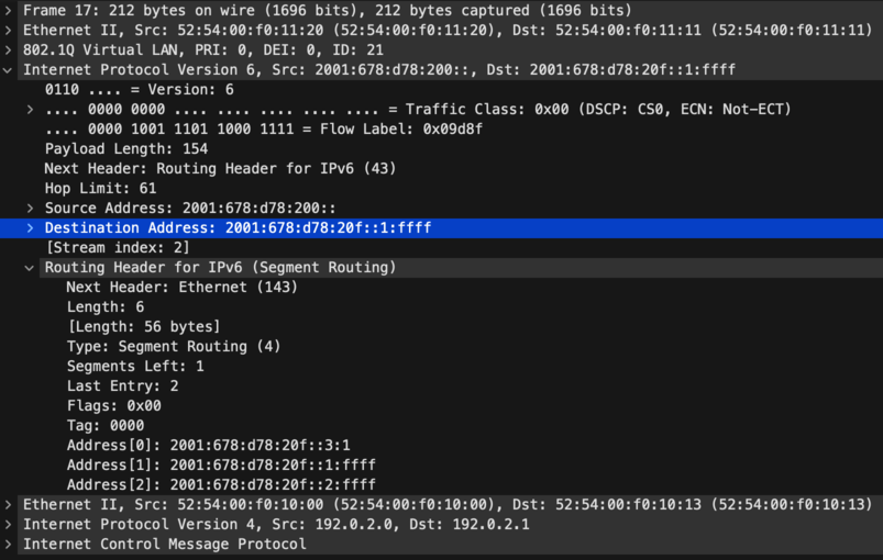
The screenshot shows the packet observed on step 4 above - it is coming from vpp0-0’s loopback address and
destined to the End localsid on vpp0-1, and I can see that the SRH has the list of 3 Segments in
reversed order, where Address[0] is the final destination: a LocalSID on vpp0-3 configured as End.DX2. I
can also see that Segments Left is set to 1.
VPP has a few relevant dataplane nodes:
- sr-pl-rewrite-encaps-l2: This node encapsulates ethernet at the ingress point by steering packets into an SR Policy named by its Binding Segment ID
- sr-localsid: This node implements End behavior, in this case sending to the next Segment Router by looking up its Local Segment ID in the FIB
- sr-localsid-d: This node decapsulates the ethernet, on an
End.DX2behavior, by looking up its Local Segment ID in the FIB
VPP: Adding SRv6 encap/decap on sub-interface
A few years ago, I thought maybe it’d be cool to use SRv6 for L2VPN at IPng. But I was quickly
disappointed because SRv6 encap and decap is only implemented on the device-input path which means
it will not work with sub-interfaces.
A few weeks ago, I worked on Gerrit [44654], which implements policers on sub-interfaces. I wrote about it in a [policer article], but since my brain’s instruction cache is still warm with the code I wrote to enable L2 features on input- and output, I thought I’d give it another go. If you’re not interested in the software engineering parts, you can stop reading now :-)
0. Remove vlan_index everywhere
The original author followed the RFC, where there is an End.DX2V behavior that allows to
decapsulate to a VLAN tag on an interface, but they never implemented it and added a note to the
code to that effect. I can see why, DX2V is not idiomatic for VPP, but there’s an alternative. It
would make more sense to decapsulate with End.DX2 to a sub-interface. So I removed this from the
codebase in all places except the API functions, where I marked them as ’not implemented’, which is
true at this point anyway.
1. Add feature bitmap entries
I added L2INPUT_FEAT_SRV6 to l2_input.h. This allows me to turn on an SRv6 feature bit, and on
ingress, send L2 datagrams from l2-input node directly to sr-pl-rewrite-encaps-l2 node,
regardless of the interface being a PHY like Gi10/0/0 or a SUB like Gi10/0/0.100. It comes at a
small CPU cost though, because moving on the device-input arc directly to the encapsulation node
will skip a bunch of L2 processing, like L2 ACL, and VLAN TAG Rewriting (which doesn’t make sense on
an untagged interface anyway). But, in return I can apply SRv6 encapsulation to any interface type.
2. Precompute DX2 headerlen
In the case of an End.DX2 to a sub-interface, I need to add either 4 bytes (single tag) or 8 bytes
(QinQ or QinAD double tag) to the packet length. I know which at creation time, because I can look
that up from the to-be-DX2’d interface. I’ll store this in the localsid structure as ls->l2_len
(either 14, 18, or 22 bytes).
3a. Connect to l2-input on ingress
When enabling the sr steer with keyword encap, I need to change two things: first, I need to
allow VNET_SW_INTERFACE_TYPE_SUB in addition to the already present
VNET_SW_INTERFACE_TYPE_HARDWARE, and then if the steer policy is SR_STEER_L2, I remove the bits
which initialize the feature arc on device-input, and instead, call
set_int_l2_mode() in MODE_L2_XC (cross connect), but then I sneakily clear the feature bitmap
bit for L2INPUT_FEAT_XCONNECT, and instead set my new L2INPUT_FEAT_SRV6 bit. This means that
from now on, any L2 frames will get sent to node sr-pl-rewrite-encaps-l2 instead of l2-output
which is what the L2XC would’ve done. Finally, I initialize the L2 feature bitmap next-nodes for the
encapsulation node in function sr_policy_rewrite_init().
3b. Connect to l2-output on egress
I call l2output_create_output_node_mapping() on the (sub)-interface, so that traffic into it will
go to l2-output, where I can inspect the feature bitmap to see if I need to send it to
decapsulation or not. I also need to update sr_localsid_next to remove interface-output and
replace it with l2-output so that egress traffic visits l2-output. In
end_decaps_srh_processing(), I need to set the l2_len on the buffer, and change the next node to
be SR_LOCALSID_NEXT_L2_OUTPUT instead of SR_LOCALSID_NEXT_INTERFACE_OUTPUT, so that
sub-interface processing can occur (eg, VLAN Tag Rewriting, ACLs, SPAN, and so on).
4. Fix a bug in sr_policy_rewrite_encaps_l2
I kind of thought I would be done, and it did work, but I had about 75% packet loss and iperf
performance was 20Mbps or so, while on the bench I usually expect 350+ Mbps. I scratched my head a
little bit, but then found a bug in the quad-loop processing of sr_policy_rewrite_encaps_l2().
Maybe you can spot it too?
  if (vec_len (sp0->segments_lists) == 1)
    vnet_buffer (b0)->ip.adj_index[VLIB_TX] = sp0->segments_lists[0];
  else {
    vnet_buffer (b0)->ip.flow_hash = flow_label0;
    vnet_buffer (b0)->ip.adj_index[VLIB_TX] = sp0->segments_lists[(vnet_buffer (b0)->ip.flow_hash & (vec_len (sp0->segments_lists) - 1))];
  }

  if (vec_len (sp1->segments_lists) == 1)
    vnet_buffer (b1)->ip.adj_index[VLIB_TX] = sp1->segments_lists[1];
  else {
    vnet_buffer (b1)->ip.flow_hash = flow_label1;
    vnet_buffer (b1)->ip.adj_index[VLIB_TX] = sp1->segments_lists[(vnet_buffer (b1)->ip.flow_hash & (vec_len (sp1->segments_lists) - 1))];
  }
Once I found this, I became quite certain that nobody uses L2 encapsulation in VPP, because if 4+
packets would be present in the vector, for the second through fourth packet (b1-b3), and if the
segment list had length 1, then the segment list index would incorrectly be set to garbage
segment_lists[1] rather than the first and only segment segment_list[0]. Yikes! But it explains
perfectly why I had roughly 75% packetloss, lots of TCP retransmits, and terrible throughput. I fix
this bug and SRv6 encap starts to work flawlessly.
5. Add tests
I decide to add four tests: for {PHY, SUB} x {Encap, Decap}. On the encap side, I create a SR
Policy with BSID a3::9999:1 which encapsulates from source a3:: and sends to Segment List
[a4::, a5::, a6::c7]. I then steer L2 traffic from interface pg0 using this BSID. I’ll
generate a packet and want to receive it from pg1 encapsulated with the correct SRH and
destination address. On the decap side, I create an SRv6 packet and send it into pg1, and want to
see it decapsulated and exit on interface pg0.
I try to get consistency by adding a send_and_verify_pkts() which takes an argument as a validator
function, either compare_rx_tx_packet_T_Encaps_L2() or compare_rx_tx_packet_End_DX2(). These
four tests succeed, look at me!
==============================================================================
SRv6 L2 Sub-Interface Steering Test Case [main thread only]
==============================================================================
Test SRv6 End.DX2 decapsulation to a hardware (phy) interface.      1.53 OK
Test SRv6 End.DX2 decapsulation to a sub-interface (VLAN).          1.00 OK
Test SRv6 L2 encapsulation on a hardware (phy) interface.           1.97 OK
Test SRv6 L2 encapsulation on a sub-interface (VLAN).               1.93 OK

==============================================================================
TEST RESULTS:
    Scheduled tests: 4
     Executed tests: 4
       Passed tests: 4
==============================================================================
Results
With this change, it becomes possible to sr steer into a sub-interface, and to have an sr localsid that outputs to a sub-interface, which I can demonstrate like so:
vpp0-0# create sub-interfaces GigabitEthernet10/0/2 100
vpp0-0# set int l2 tag-rewrite GigabitEthernet10/0/2.100 pop 1
vpp0-0# set int state GigabitEthernet10/0/2.100 up
vpp0-0# sr policy add bsid 8298::2:2 next 2001:678:d78:20f::3:2 encap
vpp0-0# sr steer l2 GigabitEthernet10/0/2.100 via bsid 8298::2:2
vpp0-0# sr localsid address 2001:678:d78:20f::0:2 behavior end.dx2 GigabitEthernet10/0/2.100

vpp0-3# create sub-interfaces GigabitEthernet10/0/3 200
vpp0-3# set int l2 tag-rewrite GigabitEthernet10/0/3.200 pop 1
vpp0-3# set int state GigabitEthernet10/0/3.200 up
vpp0-3# sr policy add bsid 8298::2:2 next 2001:678:d78:20F::2 encap
vpp0-3# sr steer l2 GigabitEthernet10/0/3.200 via bsid 8298::2:2
vpp0-3# sr localsid address 2001:678:d78:20f::3:2 behavior end.dx2 GigabitEthernet10/0/3.200
One thing to remember, is that when sub-interfaces are created and used in L2 mode, they have to get the [VLAN Gymnastics] applied to them. In VPP terminology, it means applying VTR or VLAN Tag Rewrite feature, where the tag is removed upon ingress, and re-added on egress. That way, the ethernet frame that gets put into the SRv6 L2VPN is untagged. It allows me to have different encapsulation on both sides.
Now, for the moment suprème, on the two hosts, I can now create this sub-interface and use the tagged L2VPN also:
root@host0-0:~# ip link add link enp16s0f0 name enp16s0f0.100 type vlan id 100
root@host0-0:~# ip link set enp16s0f0.100 up mtu 1500
root@host0-0:~# ip addr add 192.0.2.128/31 dev enp16s0f0.100

root@host0-1:~# ip link add link enp16s0f3 name enp16s0f3.200 type vlan id 200
root@host0-1:~# ip link set enp16s0f3.200 up mtu 1500
root@host0-1:~# ip addr add 192.0.2.129/31 dev enp16s0f3.200
root@host0-1:~# ping 192.0.2.128
PING 192.0.2.128 (192.0.2.128) 56(84) bytes of data.
64 bytes from 192.0.2.128: icmp_seq=1 ttl=64 time=9.88 ms
64 bytes from 192.0.2.128: icmp_seq=2 ttl=64 time=4.88 ms
64 bytes from 192.0.2.128: icmp_seq=3 ttl=64 time=7.07 ms
^C
--- 192.0.2.128 ping statistics ---
3 packets transmitted, 3 received, 0% packet loss, time 2003ms
rtt min/avg/max/mdev = 4.880/7.273/9.876/2.044 ms

root@host0-1:~# ip nei | grep 200
192.0.2.128 dev enp16s0f3.200 lladdr 52:54:00:f0:10:00 REACHABLE
fe80::5054:ff:fef0:1000 dev enp16s0f3.200 lladdr 52:54:00:f0:10:00 DELAY
What’s Next
I’ve sent the change, which is about ~850 LOC, off for review. You can follow along on the gerrit on [44899]. I’m happy to have fixed the quad-loop encap bug, but it does show me that SRv6 (at least in L2 transport mode) is not super common for VPP, perhaps not common in the industry? I am not convinced that I want to use this in production on AS8298, but if I did, the basic functionality would be adding an IPv6 prefix to each of the loopback devices, in order to attract traffic to the router, add an ‘End’ localsid on every router so that they can participate in multi-hop SRv6, and add some static config to [vppcfg] to do the encap/decap for L2VPN. By the way, there’s a whole world of encap and decap behaviors, including L3VPN for IPv4, IPv6, GTP-U, and so on.
For me, I’ve still set my sights on eVPN VxLAN as a destination, because that will give me multi-point ethernet mesh akin to VPLS. However there’s a lot of ground to cover for me, considering IPng uses Bird2 as a routing controlplane. Bird2 is starting to get eVPN support, but there’s a lot for me to learn. Stay tuned!